The Return Path: What Flows in the Neutral With a Single-Phase Rectifier
The question
In textbook models the neutral is an ideal reference node. In a real LV network it is a conductor with its own impedance, and it carries two different things: the imbalance of the fundamental currents and the zero-sequence harmonics injected by non-linear loads. This study separates the two with one rectifier load and a phase transfer.
Model
A three-phase source with a grounded star feeds three phases through a weak LV line (Figure 1). Each phase has an R-L load; a single-phase rectifier is connected to phase B and returns to ground through an explicit neutral impedance ZN. At 0.20 s phase B opens, and at 0.21 s its node is tied to phase A.
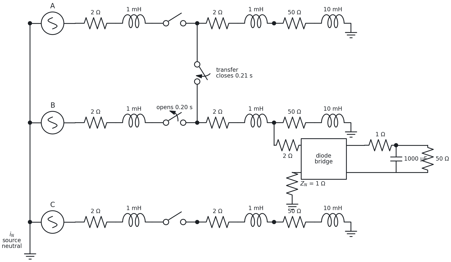
| Element | Value |
|---|---|
| Source | 220 V RMS phase (311 V peak), star grounded |
| Line | two sections of 2 Ω + 1 mH per phase (4 Ω + 2 mH in total) |
| Loads | 50 Ω + 10 mH per phase (5.8 A peak) |
| Rectifier | full bridge, fed through 2 Ω; DC: 1 Ω, 1000 µF, 50 Ω |
| Neutral impedance ZN | 1 Ω, in the return of the rectifier |
| Transfer | phase B opens at 0.20 s; its node is tied to phase A at 0.21 s |
| Simulation | 1 µs step, 0.4 s |
Results
With the rectifier on phase B
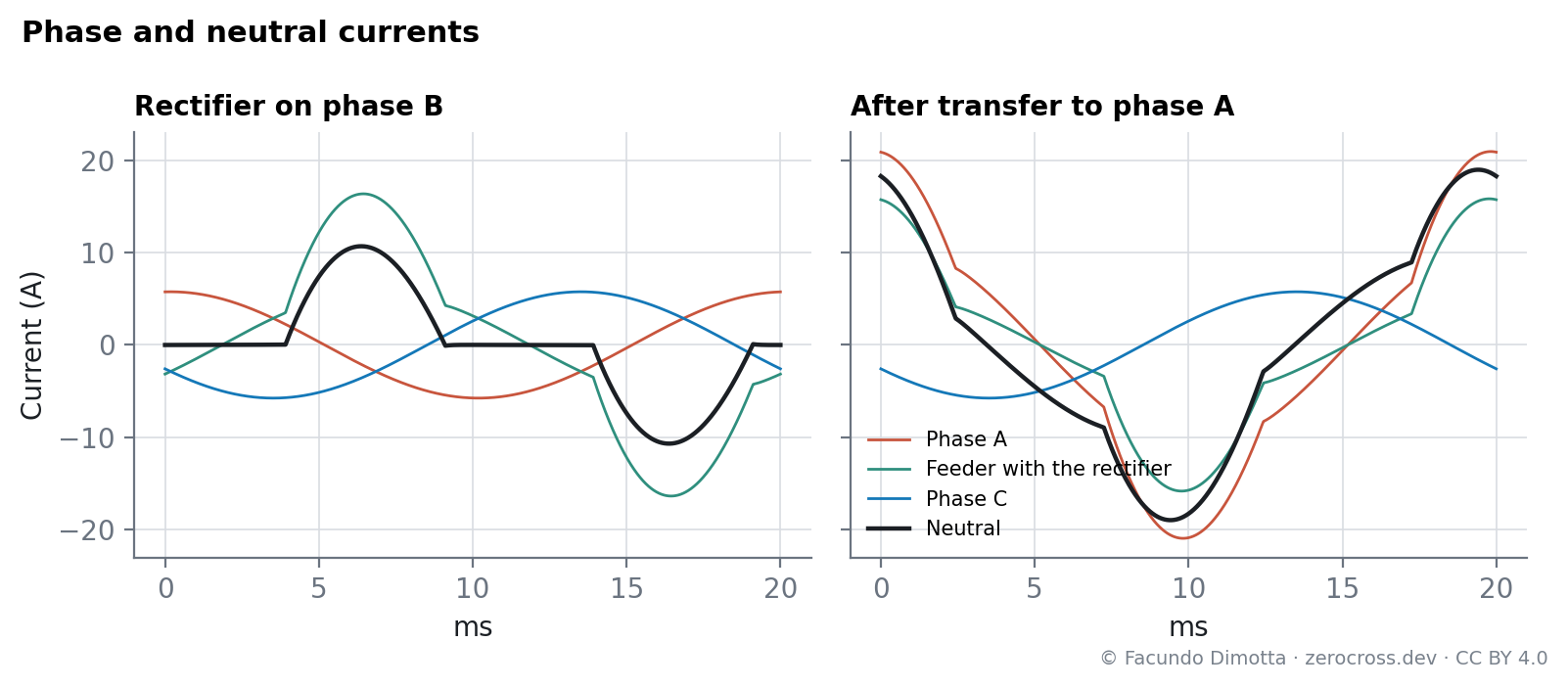
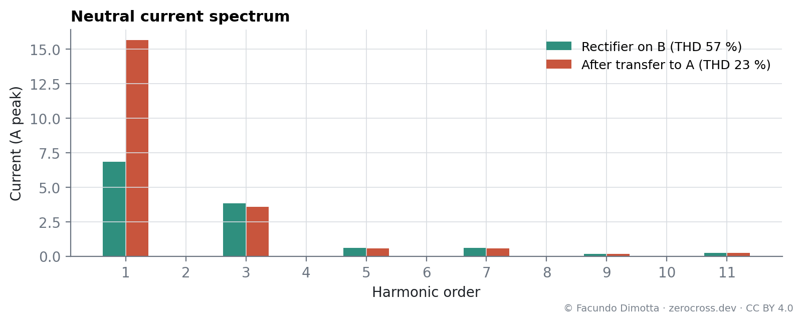
The three R-L loads are balanced, so their currents cancel in the neutral. What remains is the rectifier current: the neutral carries 6.9 A of fundamental and 3.8 A of third harmonic, a THD of 57 % (Figure 2, left). The third harmonic is more than half of the fundamental.
After the transfer to phase A
Phase A now feeds its own load, the load of the B node and the rectifier; phase B carries nothing. The imbalance raises the neutral fundamental to 15.6 A, while the third harmonic stays at 3.6 A, because it still comes from the same single rectifier (Figure 3). The THD drops to 23 %, not because there is less harmonic current, but because the fundamental grew.
Voltage at the load
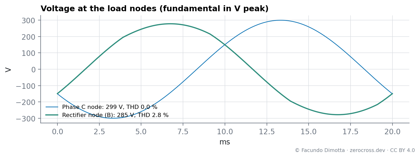
With 4 Ω of line per phase, the node that feeds the rectifier drops to 285 V peak (fundamental) against 299 V at a node with only the R-L load, and shows a voltage THD of 2.8 %, almost all third harmonic (Figure 4). The rectifier return current, about 12 A peak, also raises the voltage across ZN to about 12 V peak.
Discussion
- The neutral carries two different currents. The fundamental component depends on how balanced the phases are; the triplen harmonics depend on the non-linear loads. A transfer that worsens the balance can multiply the first without changing the second, as in this case.
- Triplen harmonics add up in the neutral. Third harmonics from loads on different phases are in phase with each other, so they add instead of cancelling. With a single rectifier, the neutral simply carries all of its third harmonic. With one rectifier per phase, the neutral third harmonic would be about three times larger even with perfectly balanced loads. That is the natural next case to simulate.
- Neutral point displacement needs a weak neutral. In this model the source star is solidly grounded and the loads return directly to ground, so the star point does not move. Studying displacement and overvoltages on lightly loaded phases requires modeling the neutral conductor itself, with its impedance, along the feeder.
Limitations
- The neutral impedance is modeled only in the rectifier return; the R-L loads return directly to ground.
- At t = 0 the neutral current shows a 3.1 kA spike lasting a single time step (1 µs). It is an initialization artifact (the DC capacitor starts charged while the rest of the circuit starts at zero) and is excluded from the analysis.
- One rectifier; no interaction between several non-linear loads.
2026-09-23. Model updated and publication rewritten:
- The “linear” loads were series RLC branches with 5 µF, which made them capacitive; they are now R-L.
- Node labels were crossed with respect to the sources; corrected.
- The 3 kA spike was previously described first as a real inrush and later as the energization of a discharged capacitor. It lasts one time step and is an initialization artifact.
- Neutral point displacement and flat-topping were described as results; the model does not show them. They are now discussed as the subject of a future case.
- Figures regenerated from the simulation data.
Reuse
Citation
@online{dimotta2026,
  author = {Dimotta, Facundo},
  title = {The {Return} {Path:} {What} {Flows} in the {Neutral} {With} a
    {Single-Phase} {Rectifier}},
  date = {2026-03-17},
  url = {https://zerocross.dev/posts/2026-03-17-neutral-return-path/},
  langid = {en}
}